Electro-Magnetic Acoustic Transmission (EMAT)
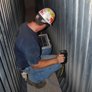
Using EMAT technique with panametric probes, MEGATECH can measure the high-temperature (up to 325° C) surface thickness. Above this temperature, the thickness readings become unstable, unreliable and non-repeatable.
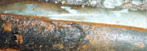
The surface for thickness measurement needs to be fairly smooth, free from rust, scale or any other kind of deposits. To get a clean surface for thickness survey, a metallic file, wire brush, small chisel and emery paper can be used for cleaning. Hammering is strictly not advisable for removal of scale/deposits. In case the above method does not yield the desired cleaning, then mechanical cleaning by power brush should be used. Under exceptional circumstances, grinding is used as a method for cleaning, with prior permission from the inspection engineer.
Thickness can be measured on painted surfaces, provided the surface paint is visible without any blisters. For critical measurement where the corrosion rate calculations are important from the remaining life point of view, paint removal is done before doing thickness survey.
Piping
For all on-site piping, corrosion loops are the basis for carrying out thickness survey whereas, for offsite and tank farm piping, special loops are made for thickness monitoring:
Each corrosion loop (for on-site piping) have a combined isometric where Thickness Management Locations (TML) are serially marked
If any base readings are taken before commissioning, it is done with random values measured on the components
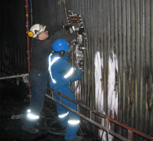
Routine, on stream or shutdown thickness measurement at these locations, is done in the form of a scanning. The scanning format is in a grid of size 1.5” x 1.5”, with each component marked with chalk before thickness scanning
Out of all the locations, few TMLs are identified for regular scanning. The selected TMLs are identified by the inspection engineer, based on the probability of corrosion at these locations (as compared to other locations in the loop) and accessibility considerations.
Respective maintenance departments provide access to ladders, scaffolding or portable trolleys for thickness scanning. In case corrosion is observed in these TMLs, then other TMLs in the loop are included for thickness scanning
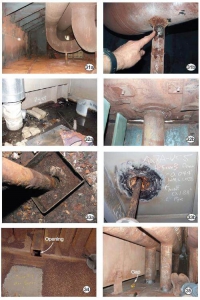
Hot Tap Locations
In case of thickness survey of equipment and piping for hot tap locations, following steps are undertaken:
The maintenance team marks the location of the new nozzle as per the exact type and dimensions of the component to be welded on the parent pipe
The Inspection engineer verifies the type of component to be welded viz. weldolet, pipe of pipe connection, a nozzle with reinforcement pad, split sleeve nozzle etc. The Inspection engineer marks the centerline of the proposed weld joint: A width of 1.5” to 2” shall be marked on either side of the proposed weld centerline. A close thickness survey is undertaken along the centerline and on either side and the minimum thickness measured is reported in the hot tap file.
If the thickness measurement is comparable to nominal or previously measured values (if available at the same locations or at different locations in the same pipe), then it could be assumed that there is no corrosion at the location.
If the thickness measurement indicates severe corrosion, and thickness measured is very close to the minimum allowable for hot tapping, then hot tapping should be avoided at the location, as it will be difficult to pick up a thickness point with minimum thickness through this procedure.
Minimum thickness required for hot tapping is 4.8mm. If the pipe is corroded and actual thickness is in the range of 6 – 8mm, then alternate methods should be used to check the pipe thickness and certify the same fit for the hot tap.
Thickness Locations In Tanks
In case of storage tanks, the thickness is measured from outside first, followed by shell course from the bottom
In all the other shell courses, the thickness is measured along the staircases. Few thickness points are taken near the weld and few at the center of the shell course plate
In case of roof plates, the thickness is measured on each plate, with two thickness points at the center of each plate and one thickness point at the corner of each plate
In case of bottom plates, thickness measurement is possible only during an internal inspection. Under this, the thickness is measured on each plate, with two thickness points at the center of each plate and one thickness point at the corner of each plate